EV Conversion Parts
Azure Dynamics AC24 Motor
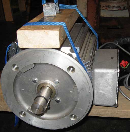
The motor weighs just under 100 lbs and will deliver around 40 HP with the 144V battery pack.
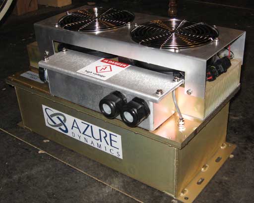
Azure Dynamics DMOC445 Controller
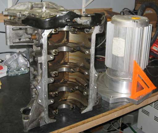
Fidanza Aluminum Flywheel
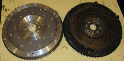
The factory flywheel (right) weighs in at over 17 lbs. It will be replaced with the Fidanza Aluminum flywheel (left) which weighs less than 9 lbs.
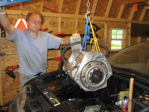
Motor and Adaptor Plate
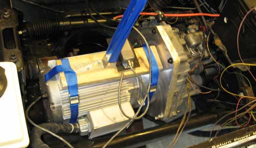
Looking down into the engine compartment from the front.
The motor and adaptor plate are lowered into the engine compartment and bolted to the transaxle. This was done so that measurements for the passenger side motor mounts could be made.
The blue staps and the 2x4 are not part of the final assembly, they're simply being used to hold the motor in place with the engine crane.
Axle and Upper Motor Mount
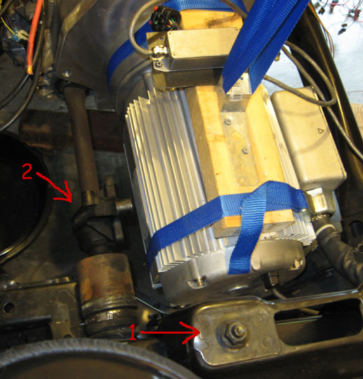
Looking down into the engine compartment from the right (passenger side).
In order to support the "back" side of the electric motor and to absorb most of the torque, some fabrication is needed.
The right side of the motor will be supported by the original upper and lower motor mounts from the Saturn. Lower motor mount point is not visible here.
1. Mounting plate for the upper motor mount.
2. The axle exits the transmission and extends to the right wheel. Originally, an intermediate shaft support bearing was bolted directly to the motor block. This bearing will be bolted to the new framework that will support the motor.
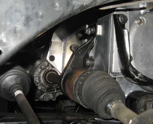
Axle and Lower Motor Mounts
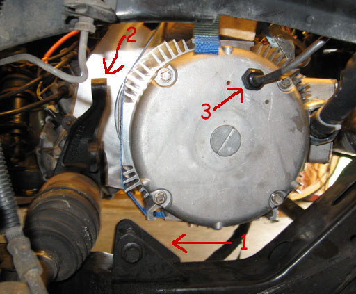
Looking in through the right wheel well with the wheel removed.
1. Lower motor mount bolt.
2. A better view of the intermediate shaft support bearing that must be fixed to the motor mounting framework.
3. A signal cable to the motor controller exits here. The framework that goes from the upper to the lower motor mounting points must avoid this cable so that it does not get damaged.
Designing a Motor Cradle
In order to accommodate the intermediate shaft support bearing and the upper and lower motor mount, a custom motor cradle was designed.
Measurements were taken from the original Saturn motor block and from the new electric motor, a wooden pattern was created out of 1/4" plywood.
Measurements were taken from the original Saturn motor block and from the new electric motor, a wooden pattern was created out of 1/4" plywood.
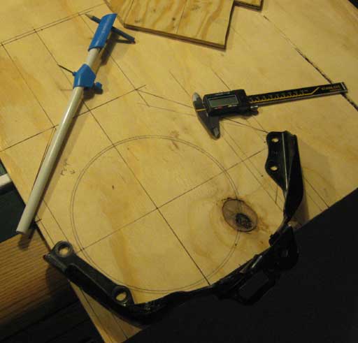
Cradle Pattern
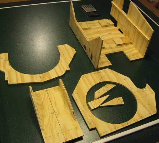
The wooden pattern was clearly labeled with the critical dimensions and then delivered to a precision metal shop that would laser cut and bend 1/4" aluminum stock into my desired pieces.
Completed Cradle
Once the parts for the cradle were cut and bent, they were taken to my local aluminum welder for assembly.
Mounting holes were drilled and tapped as needed and the entire cradle was finished off with some Scotch-Brite pads and a given a good rinsing.
Mounting holes were drilled and tapped as needed and the entire cradle was finished off with some Scotch-Brite pads and a given a good rinsing.
Motor Installed in Cradle
The motor was installed into the cradle. The hub assembly, aluminum flywheel, clutch and pressure plate were mounted onto the motor shaft. An engine crane was used to lower to motor down into the engine compartment.

The motor cradle assembly was lowered into the car and bolted to the trans-axle. The intermediate shaft support bearing, upper and lower motor mounts were bolted to their pre-drilled and tapped locations.
The intermediate shaft support bearing bolted to the cradle.