Vacuum Pump
Vacuum Booster
The Saturn originally had power brakes -- I would like to keep it that way.
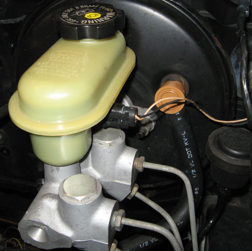
Power brakes are simply a vacuum booster (the big black round canister) located on the engine side of the firewall, behind the brake pedal. Vacuum from the engine is used to activate a diaphragm inside this canister to increase the pressure applied to the brake pedal by the driver. There is a 1/2" ID (inside diameter) hose connected to the canister by a check valve (orange). The check valve keeps vacuum in the canister so that the booster will work for a short time after the engine is turned off.
A rod transfers the boosted pressure from the brake pedal into the master cylinder (bolted onto the booster) which forces brake fluid out to each of the four brakes through two pairs of lines.
The brake fluid reservoir is the plastic tank on top of the master cylinder and near the bottom of the tank is the low fluid sensor.
Air Compressor and Tank
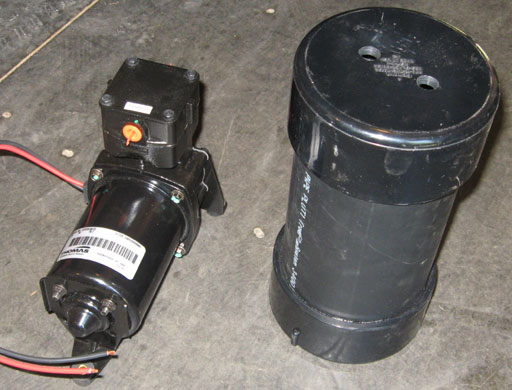
Electro Automotive provides a 12V air compressor, a tank made of PVC tubing, muffler, vacuum switch, relay, check valve and some misc brass fittings for an onboard vacuum system.
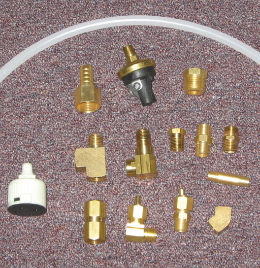
In addition to the fittings provided by Electro Automotive, I went to the local hardware store and purchased a few more fittings and some tubing to complete this installation.
More Demolition
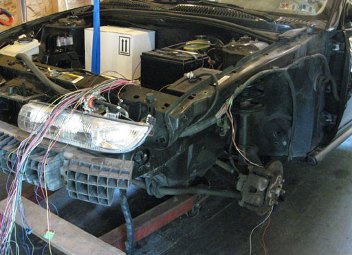
The air compressor and tank will take up a considerable amount of space. Since space under the hood will be limited, I will take advantage of some empty space in the very front driver's side of the car behind the front fender. In order to get to this space, the driver's side front fender and front bumber cover had to be removed.
Mounting the Compressor
The compressor comes with rubber shock mounts so that the entire car does not vibrate when it's running. If the compressor must be mounted in an upright position or the shock mounts will be damaged and the compressor will break loose.
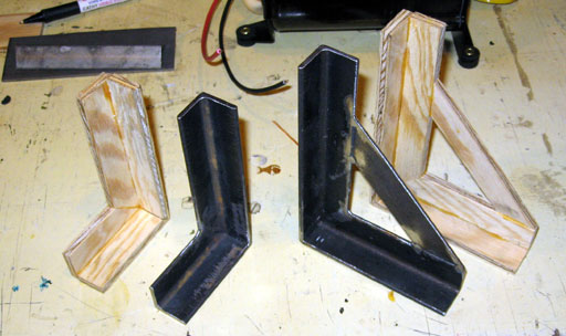
Wooden patterns were made for the compressor mounting brackets and taken to a local metal fabricator and made out of 1/8" steel.
In the picture above, you can see the wooden patterns and the brackets received from the fabricator. Also, in the background, you can see the rubber shock mount feet on the compressor.
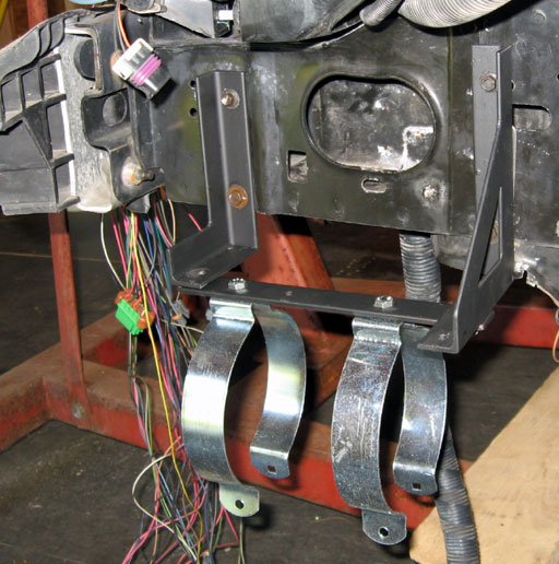
The metal brackets were drilled, sanded with a grinder, primed and painted.
The tank will be mounted below the compressor. The mounting straps for the tank are 4" electical conduit hangers. These can only be found through contractor type electrical suppliers.
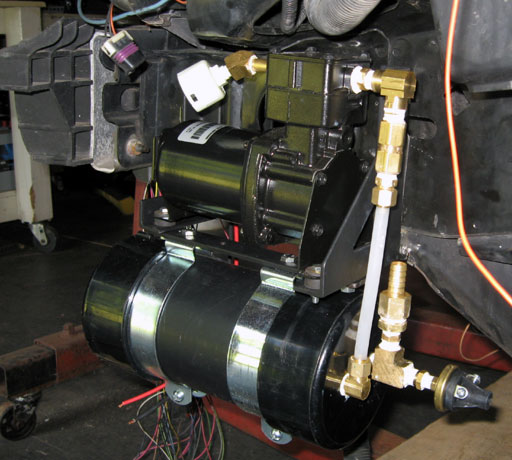
The compressor and tank are mounted and all the pieces are connected.
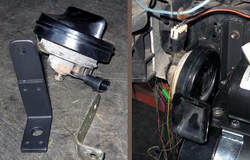
The horn needs to be moved forward and away from the car a few inches. A new horn bracket is fabricated from part of one of the old straps that held the gas tank in place.
The Schematic
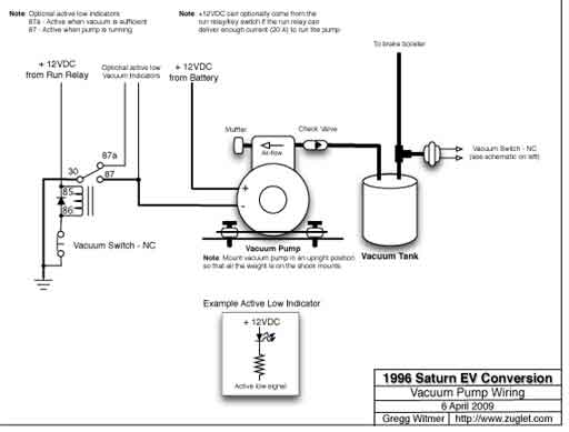
This electrical/mechanical schematic diagram was created for installing the vacuum pump. It shows how to connect the relay, pressure switch, check valve and also how to drive indicator lights on the dash.
Click here to download a printable (and readable) version of this schematic.
Click here to download a printable (and readable) version of this schematic.